Robot System Design
Designing the robot system requires various skills. We have to design and fabricate the robot structure; we also have to design the electric circuit for the robot system; further, we have to construct the control system that contains high-level controller (that generates the control input related to the overall target goal of the robot) and the low-level controller (that collects sensing data and provides motor control input under fast control loop with punctuality). Since I have constructed couple of robot systems, I am confident in constructing the robot systems using following skills.
-
3D CAD design & Fabrication (3D printer, laser printer, CNC, molding, etc.)
-
CAN Open communication for real-time motor control (multiple motors)
-
High-level control using ROS and low-level control using STM
3D CAD design & Fabrication
When we develop the robot, first thing we have to design and fabricate is the robot structure. For this reason, as a mechanical engineer, I have designed lots of mechanisms and robot structures using Solidworks. Since my research topic is about soft wearable robot, I also have an experience in fabricating the glove using the sewing machine.
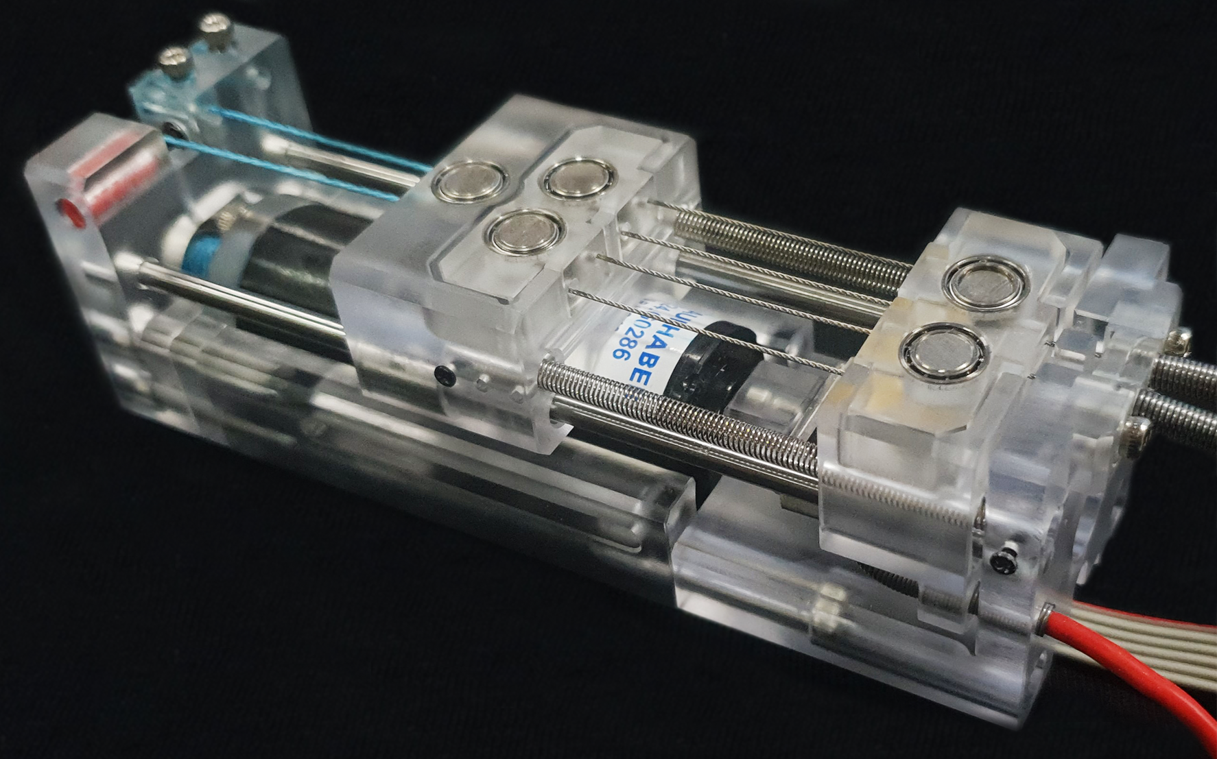
Representatively, I have designed and manufactured a tendon-driven actuator for the wearable robots. With this actuator, it was possible to operate the soft wearable robot reliabliy; the actuator (shown in Fig.1) is called “Slider-Tendon Linear Actuator” and the details are explained here.
CAN Open communication for real-time motor control (multiple motors)
Controlling the motor requires in-depth understanding on the working principle of the motor. Also, the motor requires high electric power, therefore, additional circuit is required to operate the motor. For this reason, an electric circuit called `motor driver’ has been dedicated to controlling the motor. In this way, we can control the motor in a real-time without burdening the main controller.
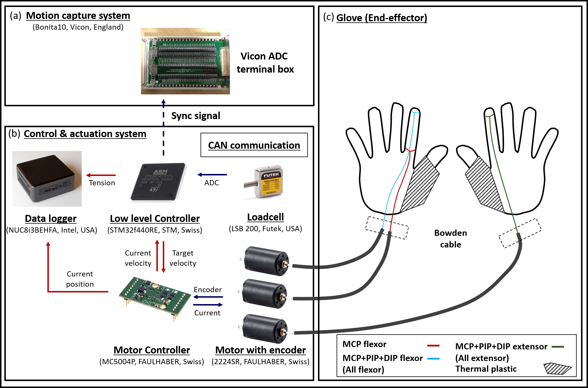
When controlling the motor using the motor driver, it is important to follow the communication protocol for the motor driver. CANOpen protocol is one of the well used communication protocol for the motor control. It is because this protocol provides researchers a variety of features to reliably control the motor in real time. I have experience controlling 4 motors with 1Khz control loop using CANOpen (Details are here.). I am also confident in constructing robot system using a high-level controller (ROS) and low-level controller(STM) with this CANOpen protocol. Details of how I constructed the high-level and low-level controller is described in below.
High-level & Low-level control
When designing the robot system, constructing an appropriate control is also important. A computer using a general operating system (linux, windows) can perform various functions, but it may not appropriate to collect sensing data or to control motors because it is not suitable for the real-time control. For this reason, I have constructed high-level controller using ROS (Robot Operating System) and low-level controller using STM (which is one of micro controller unit) to control the robot more appropriately. Since CANOpen protocol is bus-driven communication, it was also possble to simply exchange the data between high-level controller, low-level controller, and motor drivers.
PCB design
To control the robot system using the above element techniques (CANOpen, low-level controller, and high level controller), designing the electric circuit is also important. It is because the reliability of the robotic system highly depends on the electric circuit design. Therefore, using the universal board to connect all the IC chips is an inappropriate manufacturing method when we consider the roboustness of the robot system.
Alternatively, we can use a printed circuit board (PCB) for more reliable electric. For this reason, I have designed numerous PCBs using KiCAD. The Electric system in Fig.1 shows the PCB that I designed to control the motor using CANOpen protocol, low-level controller, and high-level controller. Using this PCB unit, it was possible to controll total four actuators measuring the tension of the tendon; it was used to control the Exo-Glove Shell that assists the thumb opposition/reposition and flexion/extension of the index/middle finger.

Human state measuring devices
Since I have developed numerous hand wearable devices and robots, I have used lots of experimental devices that measures human states. Mostly, I have used motion capture system from Vicon to validate the performance of the wearable robot. In addition, I have an experience measuring the EMG signal using Delsys EMG sensors to control the hand wearable robot.
For instance, as the experimental setup (Fig.2) shows, by measuring the force applied at the object (using the 6-axis loadcell called mini40) and the position/orientation of object (using Vicon motion capture cameras), I measured the grasp stability when the wearable robot assists the disabled people; details are explained here. Here, since syncing the force data with position data is important, additional trigger signal was used as shown in the Fig.2 (a).
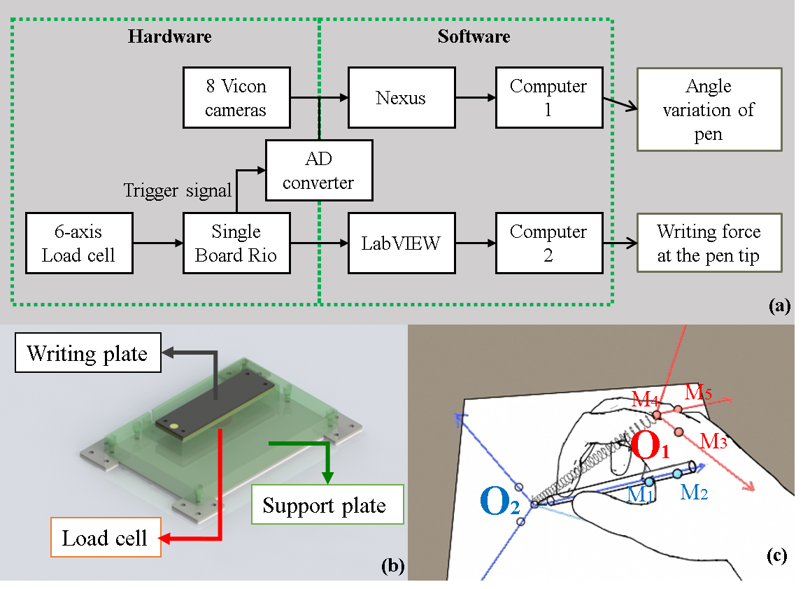
I have also conducted experiments (Fig.2) that figure out how the motor torque/position of the developed wearable robot (ExoIndex) affects the joint angle of the user; details can be found in this paper. With this experiments, I first measured position of the finger joints accurately using product of exponential (POE) theory. After that, I measured the joint angle of index finger simultaneously with tendon stroke and tension (since the robot is tendon-driven robot). With this experiment, it was possible to figure out how the finger joints move when the robot is operated; it is true that the relationship between tendon motion and human movement could be modelled before, but it was not accurate due to many uncertanties in soft wearable robots. Therefore this experiment was condcuted to figure out the relationship between tendon motion and human movement in data-driven method.